前面我们学习了specify...endspecify 具体是什么东西。今天,我们使用specify block 中定义的延时,来进行一次仿真。看看到底是背后如何运转的呢。
一 基本例子
一个用 specify 指定延迟的与门逻辑描述如下:
module and_gate(output Z,input A, B);assign Z = A & B ;specifyspecparam t_rise = 1.3:1.5:1.7 ;specparam t_fall = 1.1:1.3:1.6 ;(A, B *> Z) = (t_rise, t_fall) ;endspecifyendmodule一个用 specify 指定延迟的 D 触发器描述如下:
module d_gate(output Q ,input D, CP);reg Q_r ;always @(posedge CP)Q_r <= D ;assign Q = Q_r ;specifyif (D == 1'b1)(posedge CP => (Q +: D)) = (1.3:1.5:1.7, 1.1:1.4:1.9) ;if (D == 1'b0)(posedge CP => (Q +: D)) = (1.2:1.4:1.6, 1.0:1.3:1.8) ;$setup(D, posedge CP, 1);endspecifyendmodule顶层模块描述如下,主要功能是将与逻辑的输出结果输入到 D 触发器进行缓存。
module top(output and_out,input in1, in2, clk);wire res_tmp ;and_gate u_and(res_tmp, in1, in2);d_gate u_dt(and_out, res_tmp, clk);endmoduletestbench 描述如下,仿真时设置 "+maxdelays",使用最大延迟值。
`timescale 1ns/1ps
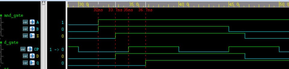
module test ;wire and_out ;reg in1, in2 ;reg clk ;initial beginclk = 0 ;forever begin#(10/2) clk = ~clk ;endendinitial beginin1 = 0 ; in2 = 0 ;# 32 ;in1 = 1 ; in2 = 1 ;# 13 ;in1 = 1 ; in2 = 0 ;endtop u_top(.and_out (and_out),.in1 (in1),.in2 (in2),.clk (clk));initial beginforever begin#100;if ($time >= 1000) $finish ;endendendmodule // test仿真时序如下所示,由图可知:
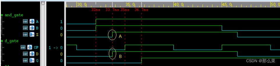
- (1) 与门输入端 A/B 到输出端 Z 的上升延迟为 33.7-32=1.7ns;
- (2) 与门输出端 Z 到触发器输入端 D 的互联延迟为 0;
- (3) 触发器 D 端到 CP 端时间差为 35-33.7=1.3ns,大于 setup check 时设置的 1ns,因此时序满足要求,不存在 violation 。
- (4) 触发器 CP 端到输出端 Q 的上升延迟为 36.7-35=1.7ns;
综上所述,仿真结果符合设计参数。
二 拓展延伸
其实,我们可以做一个延伸。修改代码如下:
module top(output and_out,input in1, in2, clk);wire res_tmp;wire res_tmp_tmp;assign res_tmp_tmp = res_tmp;specify( res_tmp => res_tmp_tmp) = (2:3:4, 3:4:5); endspecfiyand_gate u_and(res_tmp, in1, in2);d_gate u_dt(and_out, res_tmp_tmp, clk);endmodule修改上面代码,重新进行仿真,我们会发现,Z -> D 之间,将会有 4 ns 的延时存在。


![[C++] STL数据结构小结](http://pic.xiahunao.cn/nshx/[C++] STL数据结构小结)


