序:
上一节我们安装好了MPU6050的三方库,这一节我们尝试使用该库通过esp32将IMU模块驱动起来。
参考资料:小鱼——使用开源库驱动IMU
一、使用开源库驱动IMU
1. MPU6050介绍
首先我们了解下MPU6050模块,从外观看,长这个样子
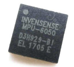
MPU6050 为全球首例集成六轴传感器的运动处理组件,内置了运动融合引擎,用于手持和桌面的应用程序、游戏控制器、体感遥控以及其他消费电子设备。它内置一个三轴 MEMS 陀螺仪、一个三轴 MEMS 加速度计、一个数字运动处理引擎(DMP)以及用于第三方的数字传感器接口的辅助 I2C 端口(常用于扩展磁力计)。当辅助 I2C 端口连接到一个三轴磁力计,MPU6050 能提供一个完整的九轴融合输出到其主 I2C 端口。
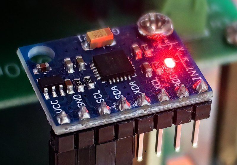
在板子上是这样的
2. 调用开源库驱动
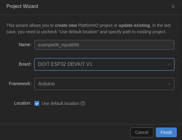
新建工程example06_mpu6050
2.1 添加依赖
修改platformio.ini
[env:esp32doit-devkit-v1]
platform = espressif32
board = esp32doit-devkit-v1
framework = arduino
monitor_speed = 115200
lib_deps = https://mirror.ghproxy.com/https://github.com/rfetick/MPU6050_light.git
2.2 样例程序
复制到main.cpp中
/* Get all possible data from MPU6050* Accelerometer values are given as multiple of the gravity [1g = 9.81 m/s²]* Gyro values are given in deg/s* Angles are given in degrees* Note that X and Y are tilt angles and not pitch/roll.** License: MIT*/#include "Wire.h"
#include <MPU6050_light.h>MPU6050 mpu(Wire);unsigned long timer = 0;void setup() {Serial.begin(9600);Wire.begin();byte status = mpu.begin();Serial.print(F("MPU6050 status: "));Serial.println(status);while(status!=0){ } // stop everything if could not connect to MPU6050Serial.println(F("Calculating offsets, do not move MPU6050"));delay(1000);mpu.calcOffsets(true,true); // gyro and acceleroSerial.println("Done!\n");}void loop() {mpu.update();if(millis() - timer > 1000){ // print data every secondSerial.print(F("TEMPERATURE: "));Serial.println(mpu.getTemp());Serial.print(F("ACCELERO  X: "));Serial.print(mpu.getAccX());Serial.print("\tY: ");Serial.print(mpu.getAccY());Serial.print("\tZ: ");Serial.println(mpu.getAccZ());Serial.print(F("GYRO      X: "));Serial.print(mpu.getGyroX());Serial.print("\tY: ");Serial.print(mpu.getGyroY());Serial.print("\tZ: ");Serial.println(mpu.getGyroZ());Serial.print(F("ACC ANGLE X: "));Serial.print(mpu.getAccAngleX());Serial.print("\tY: ");Serial.println(mpu.getAccAngleY());Serial.print(F("ANGLE     X: "));Serial.print(mpu.getAngleX());Serial.print("\tY: ");Serial.print(mpu.getAngleY());Serial.print("\tZ: ");Serial.println(mpu.getAngleZ());Serial.println(F("=====================================================\n"));timer = millis();}}
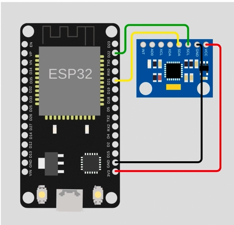
2.3 接线方法
如图所示
2.4 修改代码
- 修改波特率 9600->115200
- 修改IO地址 Wire.begin();->Wire.begin(21, 22);
#include "Wire.h"          // 导入I2C相关头文件
#include <MPU6050_light.h> // 导入MPU6050库MPU6050 mpu(Wire); // 新建MPU6050对象mpuunsigned long timer = 0;void setup()
{Serial.begin(115200);Wire.begin(21, 22); // 初始化I2C,设置sda引脚为GPIO21,SCL引脚为GPIO22byte status = mpu.begin(); // 检测IMU模块状态Serial.print(F("MPU6050 status: "));Serial.println(status);while (status != 0){} // stop everything if could not connect to MPU6050Serial.println(F("Calculating offsets, do not move MPU6050"));delay(1000);mpu.calcOffsets(true, true); // gyro and accelero 校准Serial.println("Done!\n");
}void loop()
{mpu.update();if (millis() - timer > 1000){ // print data every secondSerial.print(F("TEMPERATURE: "));Serial.println(mpu.getTemp()); // 温度Serial.print(F("ACCELERO  X: "));Serial.print(mpu.getAccX()); // X轴加速度Serial.print("\tY: ");Serial.print(mpu.getAccY()); // Y轴加速度Serial.print("\tZ: ");Serial.println(mpu.getAccZ()); // Z轴加速度Serial.print(F("GYRO      X: "));Serial.print(mpu.getGyroX()); // X轴 角速度Serial.print("\tY: ");Serial.print(mpu.getGyroY()); // Y轴 角速度Serial.print("\tZ: ");Serial.println(mpu.getGyroZ()); // Z轴 角速度Serial.print(F("ACC ANGLE X: "));Serial.print(mpu.getAccAngleX()); // X轴角加速度Serial.print("\tY: ");Serial.println(mpu.getAccAngleY()); // Y轴角加速度Serial.print(F("ANGLE     X: "));Serial.print(mpu.getAngleX()); // X角度Serial.print("\tY: ");Serial.print(mpu.getAngleY()); // Y角度Serial.print("\tZ: ");Serial.println(mpu.getAngleZ()); // Z角度Serial.println(F("=====================================================\n"));timer = millis();}
}
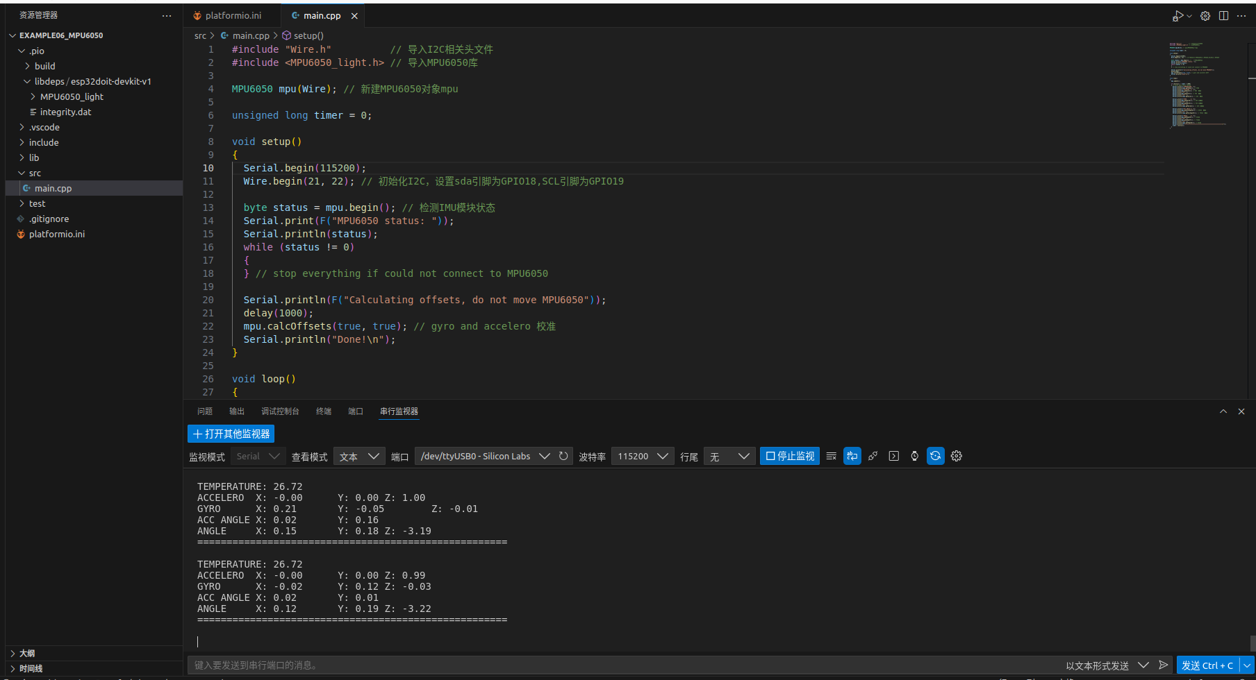
3. 编译测试
保存代码,编译下载到开发板。打开串口监视器,查看结果。
二、学会面向对象编程-封装IMU驱动
说明:在本章练习编写c++代码,建议跟着视频【ROS2硬件控制】13A.3.学会面向对象编程-封装IMU驱动(上)一步一步敲一遍,是有用的,但还没有全部理解,故暂时空下。
文档链接:学会面向对象编程-封装IMU驱动


