1.实验介绍及拓扑

(1)总部和分支机构都可以上互联网访问8.8.8.8;
(2)总部和分支机构使用广域网专线互访作为主线,并且通过互联网建立GRE隧道互访作为备线;
(3)总部内为二层架构(核心-接入),AC双链路旁挂核心,开启RSTP防环
(4)WLAN管理VLAN是100 192.168.100.1,AC和AP间cpawap隧道是VLAN100进行控制。
AP散发信号两个SSID,一个HR部门的,一个IT部门,业务数据到互联网/分支机构直接经核心交换机到出口,不经过AC
(5)总部内部和分支内部以及总部及分支间运行OSPF
2.掌握内容及配置思路
2.1掌握内容
- 配置vlan
- 配置接口类型
- RSTP
- DHCP
- 链路聚合
- NAT
- CAPWAP
- VRRP
- PPP 认证
- OSPF
2.2组网规划
2.2.1划分VLAN
| VLAN10 部门A |
| VLAN20 部门B |
| VLAN30 HR部门无线 |
| VLAN40 IT部门无线 |
| VLAN50 服务器 |
| AP1的SSID :HR |
| AP2的SSID :IT |
2.2.2配置思路
- 配置总部内网
- 配置总部-分支PPP链路认证
- 配置分支内网
- 配置总部-分支广域网OSPF
- 配置总部-分支互联网GRE
- 配置NAT
- 验证冗余性
3.配置步骤
3.1配置总部内网
3.1.1 配置服务器
步骤1:配置DNS服务器地址
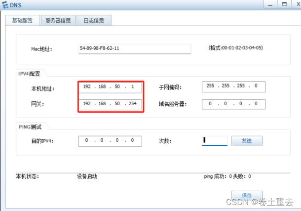
步骤2:配置WEB服务器地址

3.1.2 配置交换机VLAN和接口
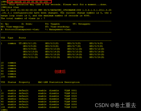
步骤1:所有交换机批量创建VLAN
vlan batch 10 20 30 40 50 100
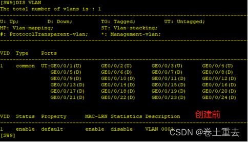
步骤2:验证创建后的VLAN
例如SW9
步骤3:配置交换机上下行二层接口
| S9 | interface GigabitEthernet0/0/1 port link-type access port default vlan 50 # interface GigabitEthernet0/0/2 port link-type access port default vlan 50 # interface GigabitEthernet0/0/3 port link-type trunk port trunk allow-pass vlan 10 20 30 40 50 100 # interface GigabitEthernet0/0/4 port link-type trunk port trunk allow-pass vlan 10 20 30 40 50 100 | #服务交换机配置接口划分VLAN50 |
| S10 | int g0/0/1 port link-type access port default vlan 10 int g0/0/2 port link-type trunk port trunk pvid vlan 100 port trunk allow-pass vlan 30 40 100 int g0/0/5 port link-type trunk port trunk allow-pass vlan 10 20 30 40 50 100 int g0/0/6 port link-type trunk port trunk allow-pass vlan 10 20 30 40 50 100 | 1口PC ,2口AP 交换机接AP的接口配置Trunk默认VLAN属于VLAN100,同时允许AP下面无线终端数据业务VLAN通过 |
| S11 | int g0/0/1 port link-type access port default vlan 20 int g0/0/2 port link-type trunk port trunk pvid vlan 100 port trunk allow-pass vlan 30 40 100 int g0/0/7 port link-type trunk port trunk allow-pass vlan 10 20 30 40 50 100 int g0/0/8 port link-type trunk port trunk allow-pass vlan 10 20 30 40 50 100 | 1口PC,2口AP |
| S1 | # vlan 4 # int g0/0/3 port link-type trunk port trunk allow-pass vlan 10 20 30 40 50 100 int g0/0/5 port link-type trunk port trunk allow-pass vlan 10 20 30 40 50 100 int g0/0/7 port link-type trunk port trunk allow-pass vlan 10 20 30 40 50 100 # interface GigabitEthernet0/0/11 port link-type trunk port trunk allow-pass vlan 100 # interface GigabitEthernet0/0/22 port link-type access port default vlan 4 | #下行口 #AC口 #上行口 |
| S2 | # vlan 5 # int g0/0/4 port link-type trunk port trunk allow-pass vlan 10 20 30 40 50 100 int g0/0/6 port link-type trunk port trunk allow-pass vlan 10 20 30 40 50 100 int g0/0/8 port link-type trunk port trunk allow-pass vlan 10 20 30 40 50 100 # interface GigabitEthernet0/0/11 port link-type trunk port trunk allow-pass vlan 100 # interface GigabitEthernet0/0/22 port link-type access port default vlan 5 | #下行口 #AC口 #上行口 |
步骤4:配置核心三层互联接口
| SW1 | SW2 |
| # vlan 6 # interface Vlanif6 ip address 192.168.6.1 255.255.255.252 | # vlan 6 # interface Vlanif6 ip address 192.168.6.2 255.255.255.252 |
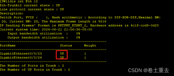
步骤5:配置Eth-trunk
SW1和SW2
#
interface Eth-Trunk12
port link-type trunk
port trunk allow-pass vlan 6 10 20 30 40 50 100
#
interface GigabitEthernet0/0/23
eth-trunk 12
#
interface GigabitEthernet0/0/24
eth-trunk 12
步骤6:验证Eth-trunk接口up
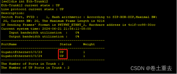
3.1.3 配置生成树RSTP
步骤1:所有交换机包括AC配置RSTP
stp mode rstp
注意:AC默认不开启生成树,所有如果同时开启了所有设备,先把AC配上生成树,避免成环。
步骤2:配置主备根桥
| SW1 | SW2 |
| stp instance 0 root primary //SW1 优先级为0, 作为根桥 | stp instance 0 root secondary //SW2优先级为4096作为备份根桥 |
配置3:验证生成树网桥ID优先级
CIST Bridge:指的就是本机的网桥ID,网桥ID是以本交换机上所有接口的最小mac地址与网桥优先级组成。
CIST root/ERPC:指的是总根的网桥ID,和到总根的开销
CIST RegRoot/IRPC:指的是域根的网桥ID,以及到域根的开销。
CIST Root PortID:指的是该交换机在CIST生成树上的根端口的端口ID


步骤4:验证生成树阻塞端口
阻塞端口为接入交换机连接核心备份根桥接口


3.1.4 配置VRRP主备网关
步骤1:配置VRRP
VRRP默认优先级100,调大为120最优,使终端网关流量走核心SW1主VRRP。
| SW1 | SW2 |
| # dhcp enable # interface Vlanif10 ip address 192.168.10.252 255.255.255.0 vrrp vrid 10 virtual-ip 192.168.10.254 vrrp vrid 10 priority 120 dhcp select global # interface Vlanif20 ip address 192.168.20.252 255.255.255.0 vrrp vrid 10 virtual-ip 192.168.20.254 vrrp vrid 10 priority 120 dhcp select global # interface Vlanif30 ip address 192.168.30.252 255.255.255.0 vrrp vrid 10 virtual-ip 192.168.30.254 vrrp vrid 10 priority 120 dhcp select global # interface Vlanif40 ip address 192.168.40.252 255.255.255.0 vrrp vrid 10 virtual-ip 192.168.40.254 vrrp vrid 10 priority 120 dhcp select global # interface Vlanif50 //服务器 ip address 192.168.50.252 255.255.255.0 vrrp vrid 10 virtual-ip 192.168.50.254 vrrp vrid 10 priority 120 # interface Vlanif100 ip address 192.168.100.252 255.255.255.0 vrrp vrid 10 virtual-ip 192.168.100.254 vrrp vrid 10 priority 120 dhcp select global # | # dhcp enable # interface Vlanif10 ip address 192.168.10.253 255.255.255.0 vrrp vrid 10 virtual-ip 192.168.10.254 # interface Vlanif20 ip address 192.168.20.253 255.255.255.0 vrrp vrid 10 virtual-ip 192.168.20.254 # interface Vlanif30 ip address 192.168.30.253 255.255.255.0 vrrp vrid 10 virtual-ip 192.168.30.254 # interface Vlanif40 ip address 192.168.40.253 255.255.255.0 vrrp vrid 10 virtual-ip 192.168.40.254 # interface Vlanif50 ip address 192.168.50.253 255.255.255.0 vrrp vrid 10 virtual-ip 192.168.50.254 # interface Vlanif100 ip address 192.168.100.253 255.255.255.0 vrrp vrid 10 virtual-ip 192.168.100.254 # |
步骤2:验证VRRP主备状态


步骤3:VRRP双主的情况
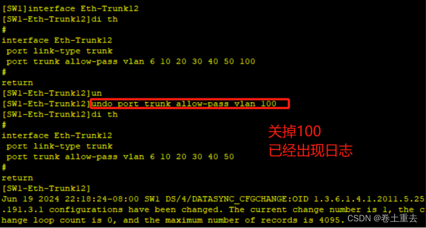
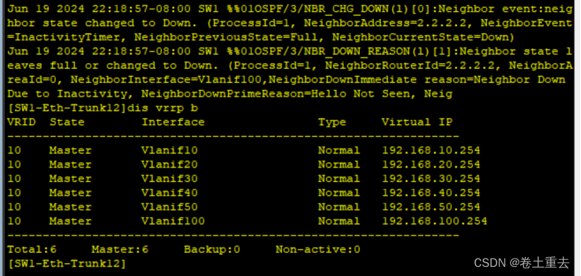
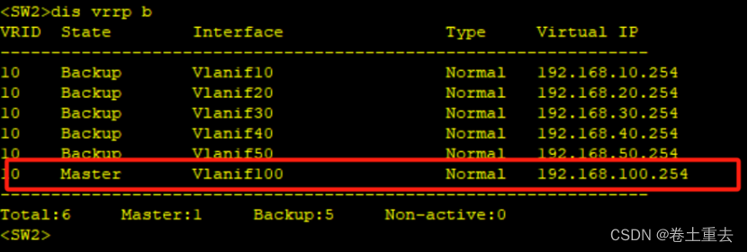
举个例子,正常情况所有master都在SW1,此时如果某备份网关vlanif100在sw2现象也是master,则称为双主情况。
为复现实验现象,使聚合接口一端配置未允许vlanif100报文通过,因为生成树的原因,会阻塞端口,导致无法交互VRRP报文,验证如下:
3.1.5 配置DHCP
步骤1:SW1创建地址池
地址池中排除252和253,因为已经被接口使用。
ip pool vlan10
network 192.168.10.0 mask 255.255.255.0
gateway-list 192.168.10.254
excluded-ip-address 192.168.10.252
excluded-ip-address 192.168.10.253
#
ip pool vlan20
network 192.168.20.0 mask 255.255.255.0
gateway-list 192.168.20.254
excluded-ip-address 192.168.20.252
excluded-ip-address 192.168.20.253
#
ip pool vlan30
network 192.168.30.0 mask 255.255.255.0
gateway-list 192.168.30.254
excluded-ip-address 192.168.30.252
excluded-ip-address 192.168.30.253
#
ip pool vlan40
network 192.168.40.0 mask 255.255.255.0
gateway-list 192.168.40.254
excluded-ip-address 192.168.40.252
excluded-ip-address 192.168.40.253
#
ip pool vlan100 //分配地址给AP,其中1分给ac, 252和253是主备网关
gateway-list 192.168.100.254
network 192.168.100.0 mask 255.255.255.0
excluded-ip-address 192.168.100.1
excluded-ip-address 192.168.100.252
excluded-ip-address 192.168.100.253
option 43 sub-option 3 ascii 192.168.100.1 //op43是为了让AP找到AC,建立CAPWAP隧道,
步骤2:验证电脑获取到地址

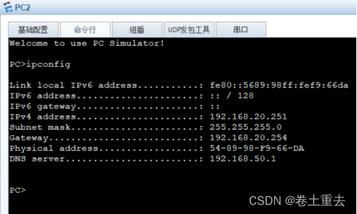
步骤3:验证AP获取到地址
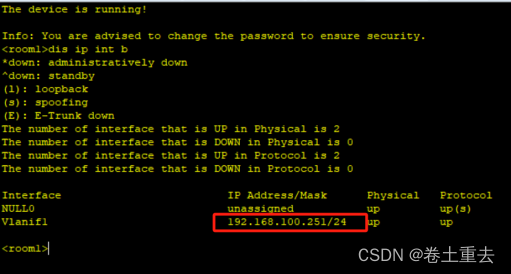
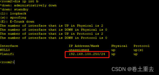
步骤4:上下流量进入AP和交换机后拆剥tag分析
这里需要特别注意以下内容:
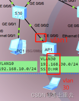
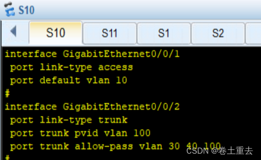
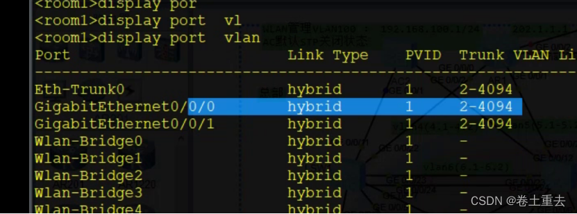
交换机SW10的g0/0/2口配置如图,接口pvid 100,trunk接口允许100通过。
- 地址池ip pool vlan100到达g0/0/2口,剥离标签pvid 100后可以分配地址给AP,此时AP的地址默认属于VLAN 1;
- 当没有数据时,AP接口g0/0/0默认是VLAN1 且是hybrid(trunk功能)口,只有控制报文capwap向上经过交换机下行g0/0/2口后打上标签pvid 100,通过capwap隧道直达AC;

- 当AP下面有笔记本流量时,因AP的wlan接口PVID是30,终端流量向上经过WLAN口会打上PVID 30,向上经过接入交换机g0/0/2接口被放行,流量到达核心交换机网关后转发至出口上互联网。
3.1.6 配置AR1与交换机互联接口
| SW1 | SW2 | AR1 |
| int vlan 4 ip add 192.168.4.1 30 | int vlan 5 ip add 192.168.5.1 30 | # interface G0/0/0 ip add 192.168.4.2 30 # interface G0/0/1 ip add 192.168.5.2 30 # |
3.1.7配置无线AC
主要理解嵌套,一般用web配置。
步骤1:基础配置
#
stp mode rstp

#
vlan 100
#
interface Vlanif100
ip address 192.168.100.1 255.255.255.0
#
interface GigabitEthernet0/0/1
port link-type trunk
port trunk allow-pass vlan 100 带标签100和AP建立capwap隧道
#
interface GigabitEthernet0/0/2
port link-type trunk
port trunk allow-pass vlan 100
步骤2:创建域管理模板,并配置国家码
WLAN
regulatory-domain-profile name default
country-code cn
步骤3:创建AP组及capwap隧道源地址
wlan
ap-group name ap-group1
regulatory-domain-profile name default
capwap source interface Vlanif 100 //AC用VLAN100和AP建立capwap隧道
步骤4:导入AP
wlan
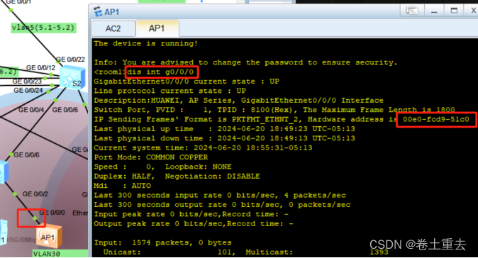
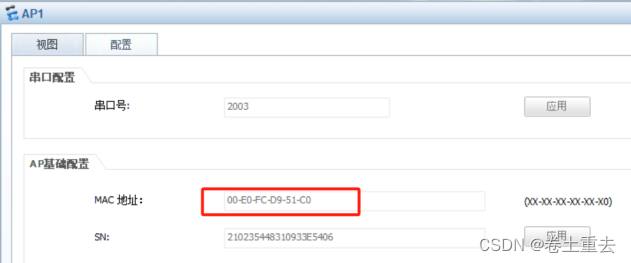
ap-id 0 ap-mac 00e0-fcd9-51c0
ap-name room1 //创建ap1
ap-group ap-group1 //ap属于ap-group1 组
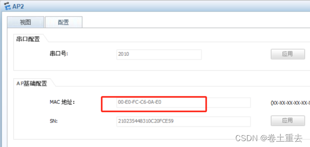
ap-id 1 ap-mac 00e0-fcc6-0ae0
ap-name room2
ap-group ap-group1
例如AP1,查看g0/0/0接口,也可直接看AP右键设置显示互相印证。
步骤5:配置安全模板
wlan
security-profile name wlan-sec //创建安全模板名称为wlan-sec
security wpa-wpa2 psk pass-phrase huawei@123 aes
步骤6:配置SSID模板
wlan
ssid-profile name HR //创建ssid 发射HR的信号
ssid HR
Info: This operation may take a few seconds, please wait.done.
ssid-profile name IT
ssid IT
Info: This operation may take a few seconds, please wait.done.
步骤7:创建VAP模板
wlan
vap-profile name HR
forward-mode direct-forward //直接转发,业务不经过AC直接走核心
service-vlan vlan-id 30
security-profile wlan-sec
ssid-profile HR
vap-profile name IT
forward-mode direct-forward
service-vlan vlan-id 40
security-profile wlan-sec
ssid-profile IT
步骤8:配置AP组引用VAP模板射频0和1都使用VAP模板
wlan
ap-group name ap-group1
vap-profile HR wlan 1 radio 0 //radio 0是2.4G radio 1是5G
vap-profile HR wlan 1 radio 1
vap-profile IT wlan 2 radio 0
vap-profile IT wlan 2 radio 1
配置后显示AP信号如下阴影
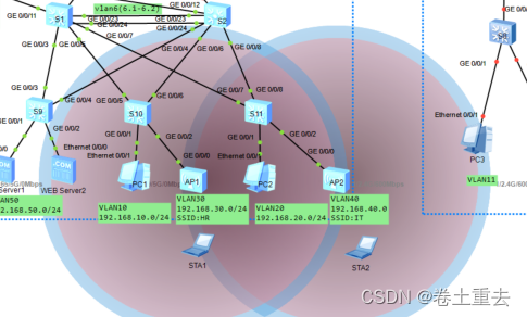
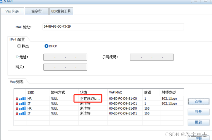
步骤9: 开启终端STA1连接WIFI获取地址
选择SSID-HR→选择2.4G信道1→连接→输入密码→显示已连接


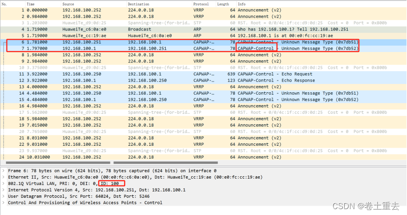
步骤10:分析报文
(1)验证capwap隧道
抓包AC接口看到AP与AC交互的capwap报文,细节包含VLAN ID100

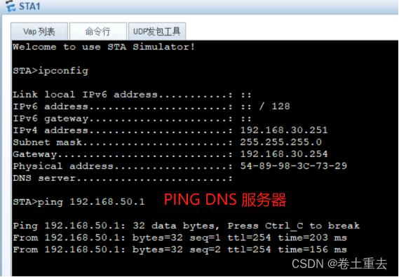
(2)验证直接转发,经过核心直接到对端
笔记本PING服务器DNS server
两个接口同时抓包
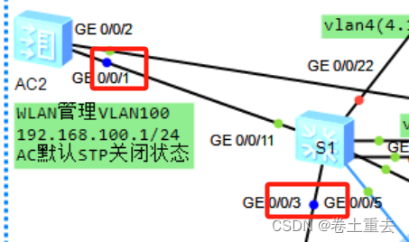
同一时间,显示S1-g0/0/3有ICMP报文,AC-g0/0/1则没有验证经过核心到达DNS服务器
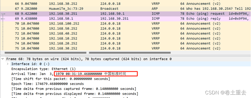
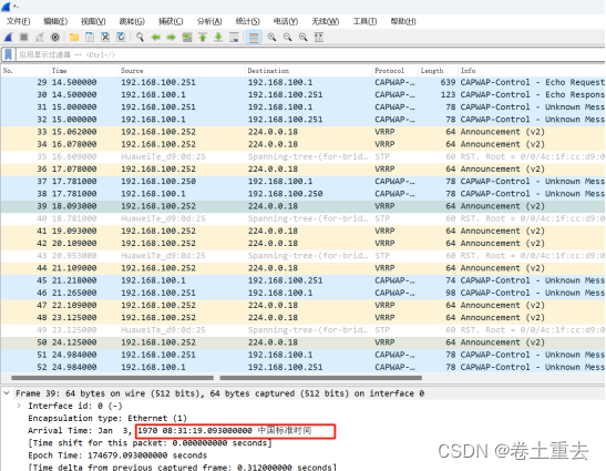
(3)验证笔记本流量上去打30标签
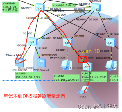
笔记本PING服务器后再AP上行口g0/0/0抓包

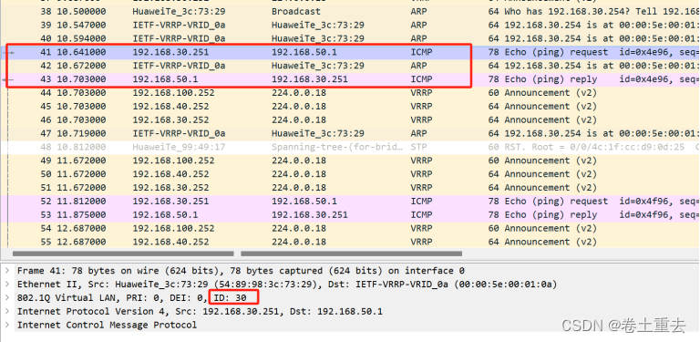
查看AP1的接口信息
起到了trunk 作用标签打上了30
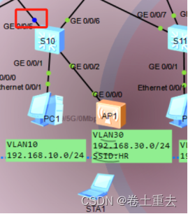
(4)验证数据未到达S10下行口是不带VLAN标签
S10-g0/0/0这里抓包capwap隧道是没有vlan id 的
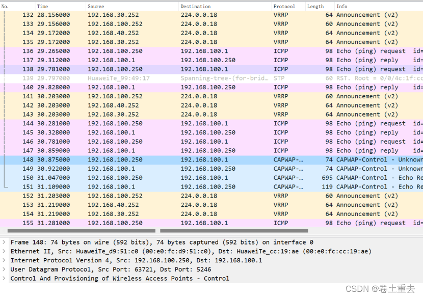
数据到达交换机下连口才打上vlan 100 经过capwap到AC G0/0/1,这里抓包S10-g0/0/6口
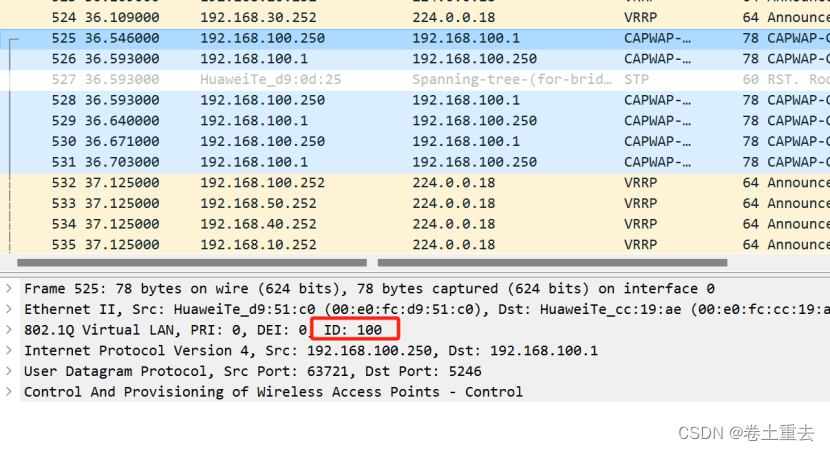
分析两种情况
- 数据直接从AP出来默认VLAN 1 ,到达交换机打上VLAN100,然后建立隧道(管理平面)
- 业务经过AP打上30,经过30带上标签,到达交换机,交换机透传30到核心,可以访问互联网或者服务器。VLAN30到达网关VRRP主。
3.2配置总部和分支广域网专线PPP链路
| AR1 | AR2 |
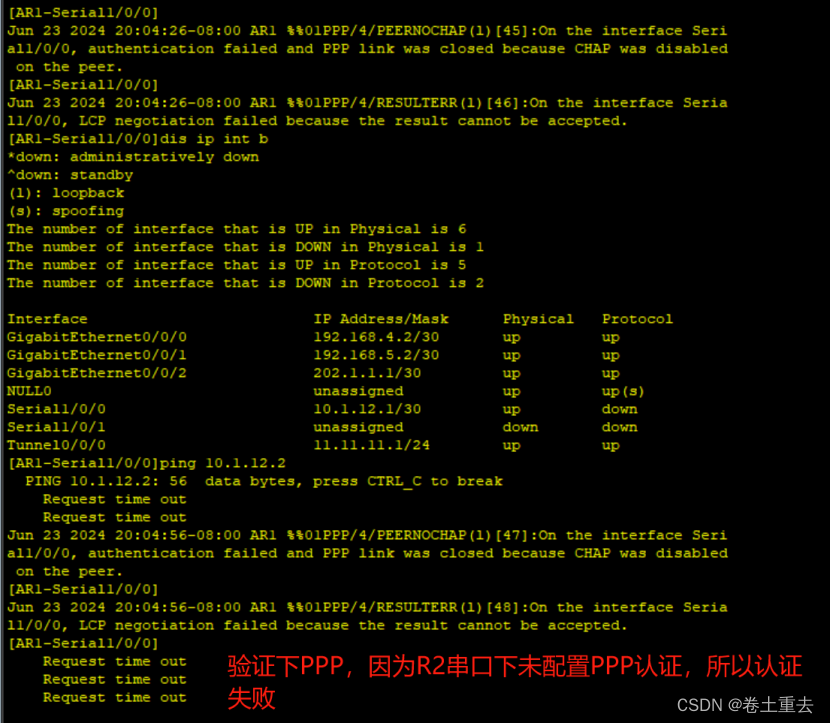
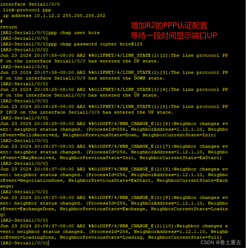
| # int s1/0/0 ip add 10.1.12.1 30 ppp authentication-mode chap quit # aaa local-user hcie password cipher hcie@123 local-user hcie service-type ppp | # int s1/0/0 ip add 10.1.12.2 30 ppp chap user hcie ppp chap password cipher hcie@123 //这里ppp配置先不配置,因为后面验证下ppp认证,此时不配置认证,串口互联口依然是通的 |
3.3分支机构配置
3.3.1分支机构核心交换机配置:
步骤1:配置三层地址
#创建VLAN 10-13
#创建Vlanif11,PC网关
#创建Vlanif12,服务器网关
#创建Vlanif13,核心与出口路由器互联地址
#
vlan batch 11 to 13
#
interface Vlanif11
ip address 192.168.11.254 255.255.255.0
dhcp select interface
#
interface Vlanif12
ip address 192.168.12.254 255.255.255.0
#
interface Vlanif13
ip address 192.168.13.1 255.255.255.252
步骤2:配置上下行二层接口
#
interface GigabitEthernet0/0/1
port link-type access
port default vlan 11
#
interface GigabitEthernet0/0/2
port link-type access
port default vlan 12
#
interface GigabitEthernet0/0/24
port link-type access
port default vlan 13
3.3.2分支机构路由器R2配置
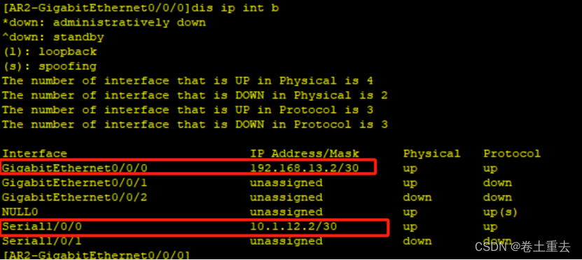
步骤1:配置到核心互联接口
interface GigabitEthernet0/0/0
ip address 192.168.13.2 255.255.255.252
步骤2:验证三层接
3.4总部与分支机构通过PPP专线实现OSPF互通
步骤1:配置总部OSPF
| SW1: | SW2: | AR1: |
| ospf 1 router-id 1.1.1.1 area 0.0.0.0 network 192.168.50.252 0.0.0.0 network 192.168.10.252 0.0.0.0 network 192.168.20.252 0.0.0.0 network 192.168.30.252 0.0.0.0 network 192.168.40.252 0.0.0.0 network 192.168.100.252 0.0.0.0 network 192.168.4.1 0.0.0.0 network 192.168.6.1 0.0.0.0 | ospf 1 router-id 2.2.2.2 area 0.0.0.0 network 192.168.50.253 0.0.0.0 network 192.168.10.253 0.0.0.0 network 192.168.20.253 0.0.0.0 network 192.168.30.253 0.0.0.0 network 192.168.40.253 0.0.0.0 network 192.168.100.253 0.0.0.0 network 192.168.6.2 0.0.0.0 network 192.168.5.1 0.0.0.0 | ospf 1 router-id 11.11.11.11 area 0.0.0.0 network 10.1.12.1 0.0.0.0 network 192.168.4.2 0.0.0.0 network 192.168.5.2 0.0.0.0 |
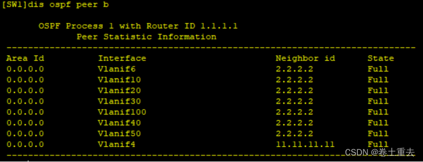
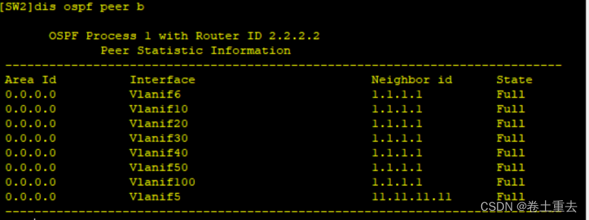
步骤2:验证OSPF邻居状态

步骤3:配置分支机构OSPF
| AR2: | SW8: | |
| ospf 1 router-id 22.22.22.22 area 0.0.0.0 network 10.1.12.2 0.0.0.0 network 192.168.13.2 0.0.0.0 | ospf 1 router-id 33.33.33.33 area 0.0.0.0 network 192.168.11.254 0.0.0.0 network 192.168.12.254 0.0.0.0 network 192.168.13.1 0.0.0.0 |
步骤4:验证OSPF邻居状态


3.5总部与分支通过互联网线路建立backup链路
正常情况下,总部和内网走广域网串口专线,当其故障后可以走互联网GRE隧道备线。
3.5.1 建立GRE隧道
步骤1:配置R1、R2、R3接口
| AR1 | AR2 | AR3 |
| # interface G0/0/2 ip add 202.1.1.1 30 | # interface G0/0/1 ip add 203.1.1.1 30 | int g0/0/1 ip add 203.1.1.2 30 # int g0/0/2 ip add 202.1.1.2 30 # int loo 1 ip add 8.8.8.8 32 |
步骤2:配置GRE隧道接口
| R1: | R2: |
| # interface Tunnel0/0/0 ip address 11.11.11.1 255.255.255.0 tunnel-protocol gre source GigabitEthernet0/0/2 destination 203.1.1.1 | # interface Tunnel0/0/0 ip address 11.11.11.2 255.255.255.0 tunnel-protocol gre source GigabitEthernet0/0/1 destination 202.1.1.1 |
步骤3:验证隧道接口是否UP
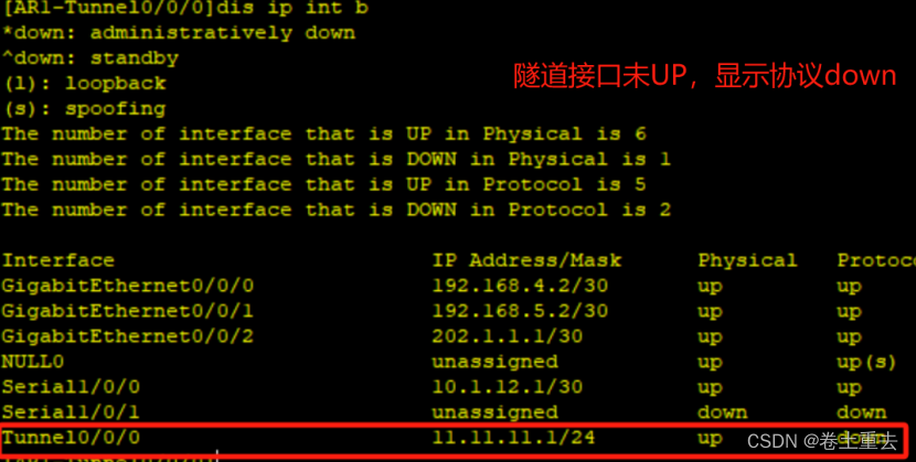
步骤4:配置静态路由
| R1: | R2: |
| ip route-static 0.0.0.0 0 202.1.1.2 # | ip route-static 0.0.0.0 0.0.0.0 203.1.1.2 # |
步骤5:验证隧道已经接口UP
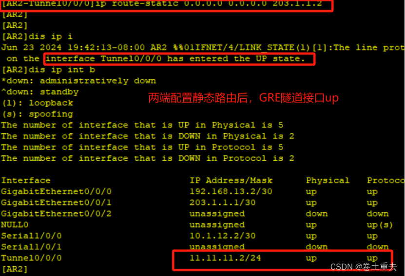
3.5.2 隧道建立OSPF并进行选路测试
总部和分支同时发布OSPF 两网段,使两者建立邻居关系。
步骤1:发布网段
| AR1 | AR2 |
| ospf 1 are 0 network 11.11.11.1 0.0.0.0 | ospf 1 are 0 network 11.11.11.2 0.0.0.0 |
步骤2:验证隧道口OSPF邻居关系
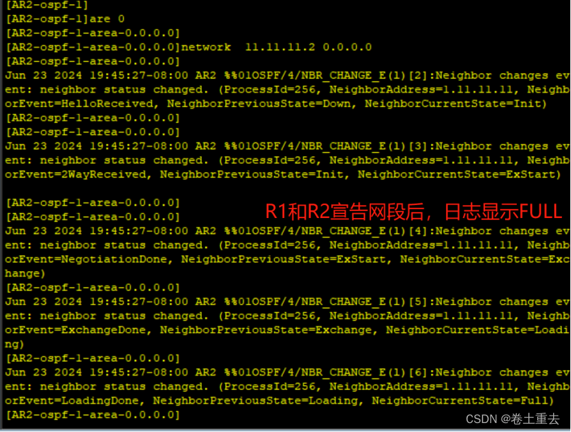

步骤3:验证AR1到分支PC走专线

从AR1上查看路由表,显示访问PC3到11网段走的广域网专线,其中cost值为50(因为串口线路48,分支内网路由器到核心是1,核心到终端是1)

步骤4:验证AR1到分支PC走互联网
现在我们模拟广域网专线故障,shutdown s1/0/0接口

查看R1路由表
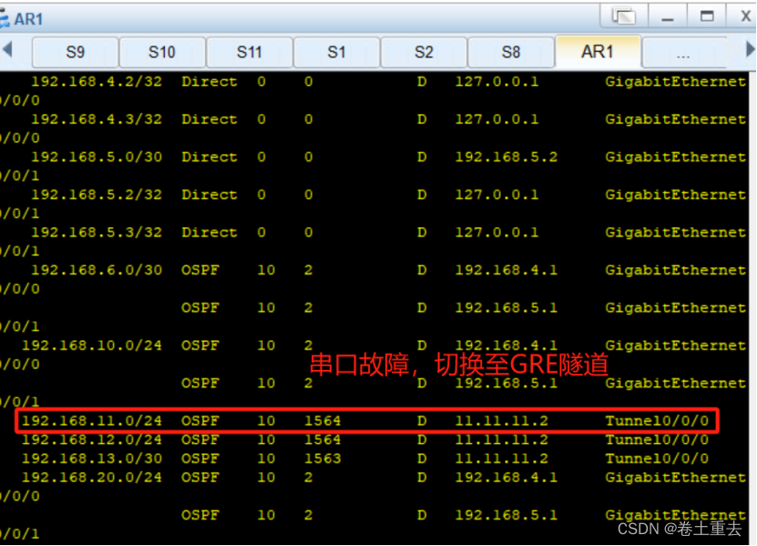
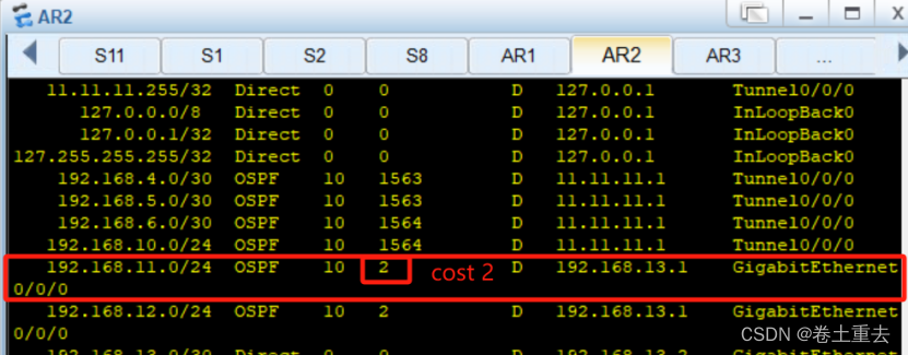
显示到11网段走隧道线路cost值是1564(隧道1562,分支内cost还有2)
R1显示如下,到11网段cost 1564

R2显示如下,到11网段cost是2
步骤5:调大OSPF cost值影响选路走专线
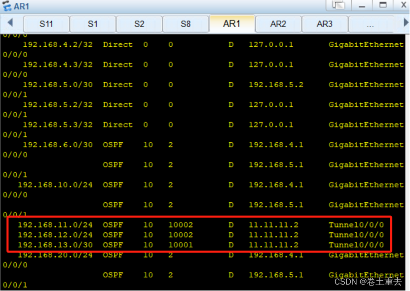
因为互联网建立隧道发布了OSPF,所以流量此时即可以走互联网线路,也可以走专线。我们需要调整OSPF开销,形成主备链路。
(1)调整开销
| AR1 | AR2 |
| # int tunnel0/0/0 ospf cost 10000 #更改隧道接口cost为 10000,作为备份链路、 | # int tunnel0/0/0 ospf cost 10000 |
(2)验证OSPF 开销

(3)切换链路至广域网专线
打开串口链路,使其走广域网串口专线50cost值(48+2)
R1
int s1/0/0
undo shutdown


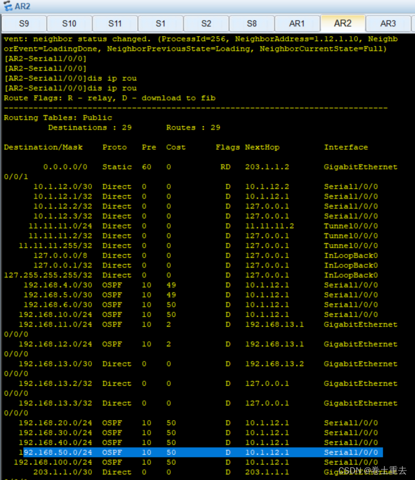
步骤6:AR2看总部服务器50网段流量走串口
步骤7:分支tracert 到服务器路径走向
(1)tracert显示走串口
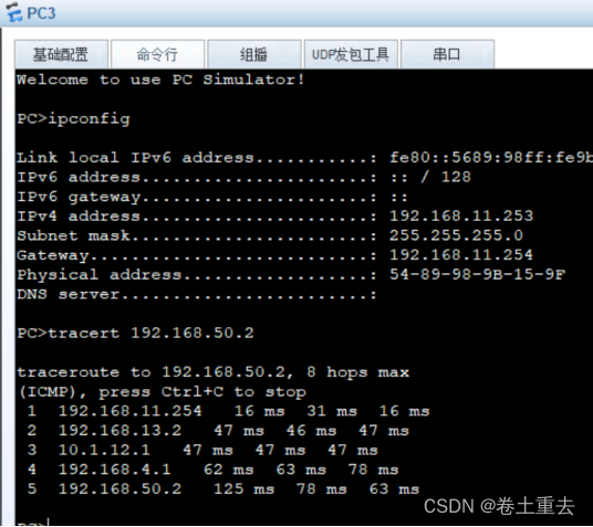
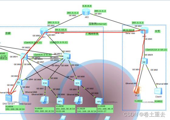
(2)模拟R2串口故障并验证路由
shutdown R2的串口

R2串口故障后显示终端有丢包
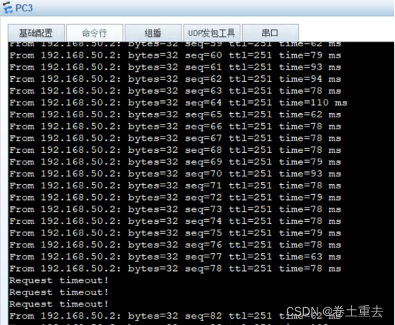
验证路由,已经切换链路

(3)恢复R2串口故障
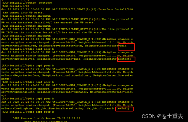
恢复后可以看到OSPF有建立过程,但 R3常PING的过程中未发现丢包现象。


)


穿三线(附带源码))